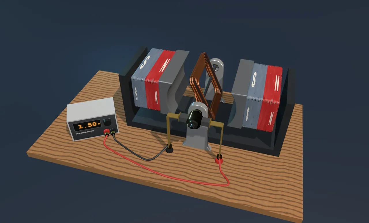
A wire that moves itself
Hold a loose wire between the poles of a strong magnet and switch a current on through it: the wire jumps sideways. Reverse the current and it jumps the other way. Turn the magnet round and it jumps the other way again. The push is at right angles both to the wire and to the field, and it grows with each of them. For a straight wire it is the field strength times the current times the length of wire in the field: F = BIL.
That jump is the whole secret of the electric motor. Everything else is about turning a sideways push into steady turning.
Two pushes make a turn
The motor in the scene has a rectangular coil of copper wire on an axle, between the curved pole pieces of two magnets. Current goes along one long side of the coil, across the end and back along the other side. The two long sides lie across the field and carry the current in opposite directions, so they are pushed in opposite directions: one up, one down. A push up on one side of an axle and a push down on the other is a twist, and the coil turns.
The forces stay the same size all the way round, but their turning effect does not. When the coil lies level, the pushes act at the full distance from the axle and the twist is strongest. As it turns upright, the pushes point straight through the axle and the twist falls to nothing. The turning effect is the force times its distance from the axle, which works out as N·B·I·A·cos θ for a coil of N turns and area A at angle θ to the field.
The commutator
Here is the problem. Once the coil has passed upright, the side that was pushed up is now on the other side of the axle. If its current still flowed the same way, the push would turn the coil back, and it would rock to a stop.
The fix is the commutator: a copper ring on the axle, split into two halves, each wired to one end of the coil. Two carbon brushes press on it from either side and carry the current in. Every half turn, just as the coil passes upright, the brushes slide across the gaps and swap halves. The current in the coil reverses, so whichever side is on the right always carries current the same way and is always pushed up. The twist never changes direction.
Try it: choose On under Show the forces and watch the commutator. Each time the brushes cross the gap, the current arrows in the coil reverse while the green force arrows keep pushing the same way round.
How fast does it go?
The twist would speed the coil up for ever if nothing pushed back. Friction in the bearings and the brushes, and the air the coil drags round, take a little more turning effect the faster it goes. The coil settles where they take all of it. Double the Current or the Magnetic field and the twist doubles, so the coil settles at twice the speed.
There is a second thing going on. A coil turning in a magnetic field is a generator: it makes a voltage of its own, the back-EMF, which pushes against the supply. To keep the current steady the supply must push harder than it would for a coil held still. That extra push, times the current, is exactly the power the motor delivers to friction, or to whatever it drives. It is how electrical energy becomes motion.
What this model leaves out
The scene slows the coil 40 times; the real one would turn about fifteen times a second at the starting settings. It treats the field as equal everywhere in the gap and the drag as growing in step with the speed, whereas real bearings also have a steady friction that can stop a weak motor dead at the upright position, where the twist vanishes. Real motors use many coils at different angles, iron in the armature to concentrate the field, and a supply that holds the voltage, not the current, so their current falls as they speed up. The brushes also spark a little as they cross the gaps, which is why many modern motors switch their currents electronically instead.