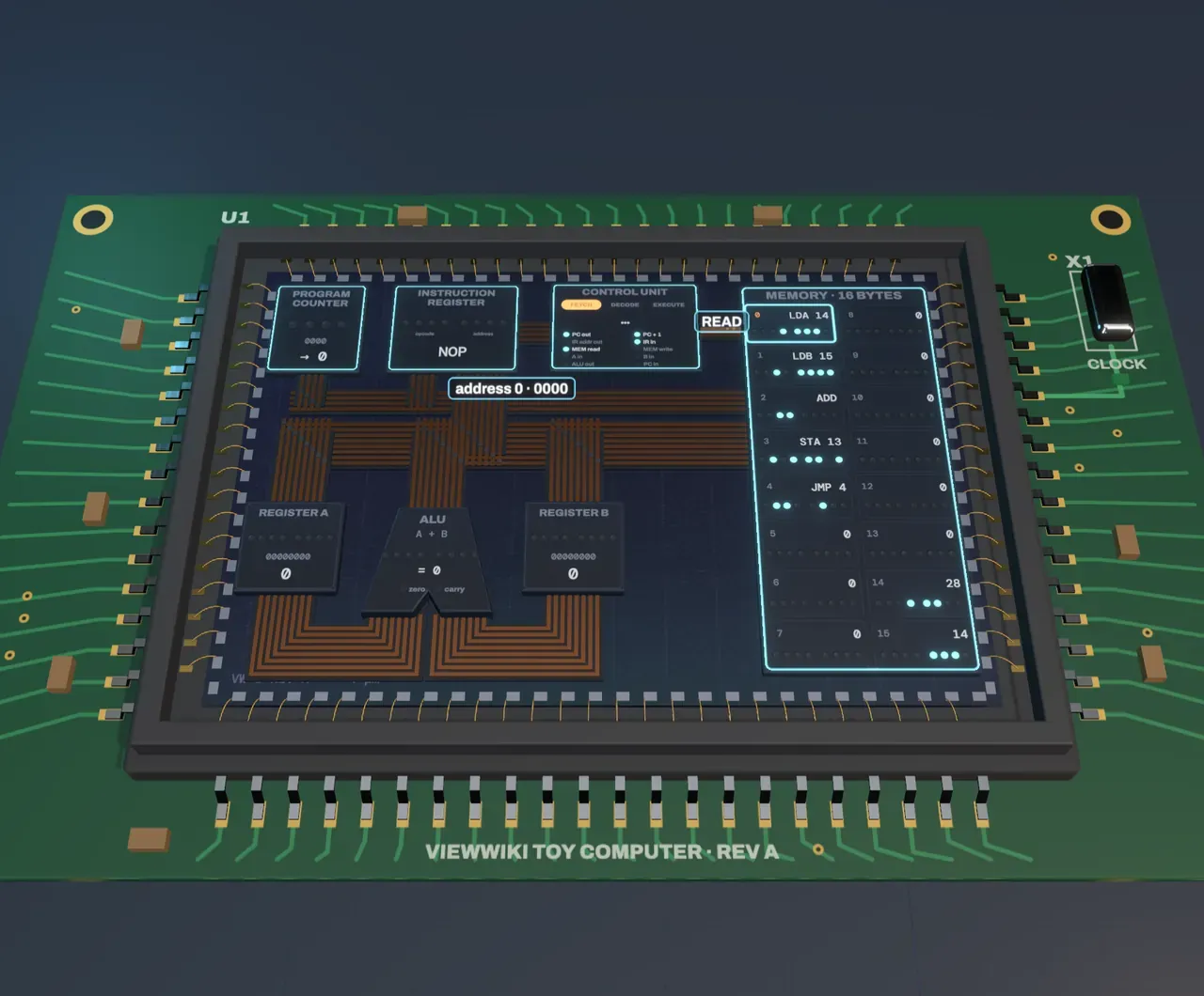
A program is numbers in memory
The memory on the right of the chip holds sixteen bytes. Five of them are the program, and three are data: two numbers to add and an empty cell for the answer. Nothing marks which is which. The byte at address 0 is 0001 1110. Read as an instruction it means load register A from address 14: the first four bits, the opcode, say what to do, and the last four say where. Read as a number it would be 30. The labels on the memory are ours; the chip only ever sees bits.
A register is a small store inside the processor that holds one value it is working on. This chip has two, A and B, each eight bits wide, so each holds a number from 0 to 255.
Fetch, decode, execute
The processor runs a program by repeating one loop, a step per tick of its clock.
Fetch. The program counter holds the address of the next instruction. It sends that address out on the address bus, memory answers with the byte stored there on the data bus, and the byte lands in the instruction register. The counter then steps on by one, ready for next time.
Decode. The control unit reads the opcode and works out which paths to open. Decoding is wiring, not thinking: each opcode switches on a fixed set of control lines, such as memory read and A in.
Execute. The control unit’s lines let exactly one value onto the data bus and tell exactly one block to keep it. A load brings a byte from memory into a register; an add lets the ALU’s answer into A; a store writes A into memory; a jump puts a new address into the program counter.
Try it: press Fetch under Clock tick and watch address 2 go out and the ADD instruction come back. Press Decode, then Execute, and follow the sum from the ALU into register A.
Buses carry numbers as voltages
Each bus is a ribbon of parallel wires, one per bit. A lit lane is a wire at a high voltage, a 1; a dark lane is a 0. The address bus here has four lanes, enough to name 16 cells; the data bus has eight, one byte. Every block can see a bus, so the control unit’s job is to make sure only one block drives it at a time and the right one listens.
The ALU, the arithmetic logic unit, is the only block that calculates. It is always adding whatever A and B hold; the control unit decides whether its answer goes anywhere. Change First number and Second number and the bits change on every lane. Slide Second number up to 240: 28 + 240 is 268, too big for eight bits, so the sum wraps around to 12 and the carry flag lights. That ninth bit is what a computer’s wider numbers are built from.
The clock keeps everyone in step
A value takes time to settle on a wire, so nothing is kept until the clock ticks. At each tick every register that has been told to listen captures what is on its inputs at once, and the next step begins. Here you move the clock yourself, and each tick’s transfers replay slowly so you can follow them. The crystal on a real board vibrates millions of times a second, and a modern processor’s clock runs at three or four billion ticks a second.
Down to transistors
Step Zoom into the chip to Transistors and a loupe opens over one bit of the ALU. Each bit of an adder is a full adder: it adds two bits and a carry from the bit below, and makes a sum bit and a carry for the bit above. This design uses 28 transistors, tiny switches whose gate decides whether current can flow through the channel beneath. An n-type transistor conducts when its gate is 1; a p-type conducts when its gate is 0. The p-types pull an output up to 1, the n-types pull it down to 0, and the circuit is arranged so exactly one side wins for every combination of inputs. The glowing channels are the switches that are on for the bits being added right now.
Every block on the chip is built from switches like these. A memory bit is a loop of six transistors that holds its state; a register bit is a few more; the decoder is gates that turn an opcode into control lines.
What this model leaves out
This is a teaching processor, simulated exactly but kept tiny. Its sixteen bytes of memory sit on the same chip; a real computer keeps billions of bytes in separate memory chips and puts small, fast caches on the processor to hold what it used recently. Real processors have dozens of registers. They pipeline, fetching the next instructions while earlier ones execute, and run several at once, so the clean fetch, decode and execute steps overlap. Every instruction here takes three ticks; real ones vary. This ALU only adds and subtracts, where a real one also does logic, shifts and comparisons.
The floor plan is laid out for reading, not copied from a real chip, and the wires are drawn hugely wide. In the loupe, the gate over each p-type and n-type pair is split to show the signal’s name; in a real layout it is one strip. A processor like this one would need a couple of thousand transistors; a modern one has tens of billions, each a few tens of nanometres across. The program ends by jumping to itself forever, a common way for a small program to stop.