On or off
A light switch has two states, and so does every part of a computer’s memory and logic: a wire is either at a high voltage or a low one. Call them 1 and 0 and each one is a bit, short for binary digit. One bit can only say yes or no, but a row of bits can stand for anything that can be counted: a number, a letter, the colour of a pixel.
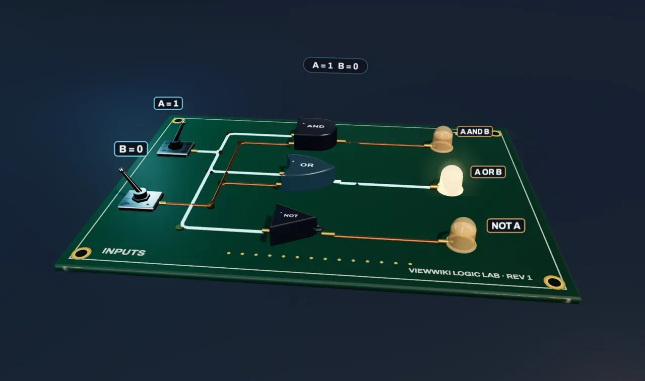
The board in the experiment has two input switches, A and B. A trace that carries a 1 glows; a trace that carries a 0 stays copper.
Gates decide
A logic gate takes one or two bits and gives back one bit by a fixed rule. Three are enough to build any computer:
- AND gives 1 only when both inputs are 1.
- OR gives 1 when either input is 1, or both.
- NOT has one input and flips it: 0 becomes 1, 1 becomes 0.
Each rule fits in a truth table, a list of every possible input with its output. With two inputs there are only four rows: 0 0, 0 1, 1 0 and 1 1. Those four rows are the four buttons of Input bits, which count from 0 to 3 in binary: the left digit is A, the right is B.
Try it: press 0 0 and only the NOT gate’s light is on. Press 1 1 and AND and OR both light while NOT goes dark.
Counting in twos
Ordinary numbers use ten digits, and each place is worth ten times the one to its right. Binary uses only 0 and 1, and each place is worth twice the one to its right: 1, 2, 4, 8 and so on. So 10 in binary means one two and no ones, which is two, and 11 means three.
Adding works as it does at school, with a carry. 0 + 0 = 0, 0 + 1 = 1, 1 + 0 = 1, and 1 + 1 = 10: write 0, carry 1.
Gates that add
Under Wire a half adder, choose Half adder and the same gates rearrange, joined by one more AND. Look at the two outputs as you flip the switches:
- The carry is 1 only when both inputs are 1. That is exactly AND.
- The sum is 1 when exactly one input is 1. No single gate does that, but OR says “at least one”, and NOT AND says “not both”. Joined by a second AND, they give “at least one, but not both”.
That rule has its own name, exclusive or (XOR), and together with the carry it makes a half adder: two bits in, their sum as a two-digit binary number out. Chain adders so that each passes its carry to the next and you can add numbers of any length. The arithmetic unit inside a processor is built this way, from millions of gates.
What this model leaves out
The board shows logic, not electronics. In a real chip each gate is a few transistors, tiny switches turned on and off by a voltage, and the most common gate is NAND (NOT AND), from which all the others can be made. Signals take time to pass through a gate, a few trillionths of a second today, and clocked circuits wait for every gate to settle before reading an answer; here the board settles at once. A real adder also needs a full adder for every column after the first, one that takes three inputs (two bits and the carry from the column before). The glowing traces and moving beads show which wires carry a 1 and which way the logic flows; real current is not a stream of beads.