One path or many
A battery pushes charge round any loop of conductor that leads from one of its ends back to the other. With one bulb there is one loop. With more bulbs there is a choice. Wire them end to end, so the current has to pass through one after another, and they are in series. Wire each one straight across the battery, so the current has several routes and each route holds one bulb, and they are in parallel.
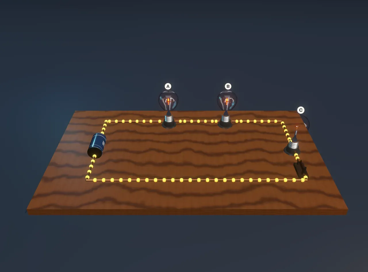
The Scene starts with bulbs A, B and C in series. All three glow a dull orange. Choose Parallel and all three blaze white, though they are the same bulbs on the same 12 V battery. The beads on the wires show the current, and they move much faster round the parallel circuit too.
Series: one current, shared voltage
In a series circuit there is only one path, so whatever current flows through A must also flow through B and C. There is nowhere else for it to go. The beads march at the same speed everywhere round the loop.
The resistances add up. Three 6 Ω bulbs in a row make 18 Ω, so the battery drives , about 0.67 A, through all of them. Each bulb takes a third of the battery’s voltage, 4 V, and turns , about 2.7 W, into heat and light. That is why they glow so dimly.
Open the switch and the one path is broken. The current stops everywhere at once, and every bulb goes out. Old strings of fairy lights worked like this: when one bulb failed, the whole string went dark and you had to test the bulbs one by one.
Parallel: full voltage, shared current
In parallel, each bulb sits on its own path from one side of the battery to the other, so each one gets the full 12 V. Each draws A and turns 24 W into heat and light. The battery has to supply all three currents at once, 6 A in total.
Every path you add gives the current another way through, so adding a bulb in parallel lowers the total resistance. Three 6 Ω bulbs in parallel make just 2 Ω:
Open the switch on C and only C’s path is broken. A and B still have their own paths across the battery and shine exactly as brightly as before. This is why the lights and sockets in a house are wired in parallel: each one gets the full mains voltage, and switching one off leaves the rest alone.
Try it: choose Parallel, then slide Resistance of bulb C from the bottom to the top. C dims, A and B do not change, and the beads in C’s branch slow down while the others keep their pace.
Kirchhoff’s two rules
Every circuit, however tangled, obeys two rules first written down by Gustav Kirchhoff in 1845. Step the Measure the circuit control to Currents and a tag over each branch shows the current in it.
The junction rule: at any point where wires meet, the current flowing in equals the current flowing out. Charge does not pile up in a wire, and it is not used up by a bulb. In the parallel circuit, 6 A leave the battery; at the first junction 2 A turn off through A and 4 A carry on; at the next, 2 A go through B and 2 A through C. Count the beads: as many arrive at a junction each second as leave it.
The loop rule: go round any closed loop and the voltage rises and falls add up to zero. Step on to Voltages and every wire is lifted to a height that stands for its voltage, measured against the scale by the battery. The battery lifts the charge by 12 V. Each bulb is a slope back down. The wires between bulbs are level, because a wire with no resistance has no voltage across it. Whichever loop you follow, you arrive back at the height you started from, so the drops round the loop add up to exactly the battery’s 12 V.
These two rules are just energy and charge being conserved. A coulomb of charge gains 12 joules in the battery and must give all of it away before it gets back.
The mixed circuit
Choose Mixed. Now A is in series with a parallel pair, B and C. All the current goes through A and then splits between B and C. The pair together has half the resistance of one bulb, 3 Ω, so the circuit has 9 Ω and draws 1.33 A. A takes 8 V of the battery’s 12 V and glows brightly; B and C share the remaining 4 V and glow dimly.
Now set Switch for bulb C to Off. You might expect everything to dim, since a bulb has been taken away. Instead B gets brighter. With C gone, B is simply in series with A, and the two share the voltage equally, 6 V each. A dims, because the total resistance has gone up to 12 Ω and less current flows through it. The loop rule explains it: A and B must still add up to 12 V, so if A’s share falls, B’s must rise.
What the model leaves out
A real filament is not a fixed resistor. Cold tungsten has about a tenth of the resistance it has when white hot, so a dim bulb has less resistance than a bright one, and the numbers here are only a guide to a real circuit. The battery here keeps exactly 12 V whatever current it supplies. A real battery has some internal resistance, so its voltage sags a little when it drives a large current, and the parallel bulbs would dim slightly as you add more. The wires are treated as perfect conductors.
The bulbs and the battery are drawn on a board as a picture, not a wiring diagram, and the gold beads are markers, not particles: they move at a speed proportional to the current so that you can compare currents by eye. Real electrons drift backwards, from − to +, at well under a millimetre a second. The heights in the voltage view are a way of drawing voltage, not anything the circuit really does; the wires stay where they are.